
A connected sensor:
from power to trustworthy data
Follow a battery-powered temperature monitor across the hardware / firmware boundary, then prove what the complete system can actually claim.
After this case study, you should be able to:
- Allocate power, sensing and data-quality responsibilities across disciplines.
- Write interface contracts that include timing, validity and recovery.
- Build an end-to-end timing and energy budget.
- Plan integration and verification that can expose a wrong system assumption.
Study guide · Updated · About 25 minutes reading + 30 minutes practice
Before you start: TEA-101 System Architecture, TEA-103 Sensing and TEA-104 Interfaces. Use the linked foundation lessons whenever a topic is unfamiliar.
One monitor, three places where meaning can be lost.
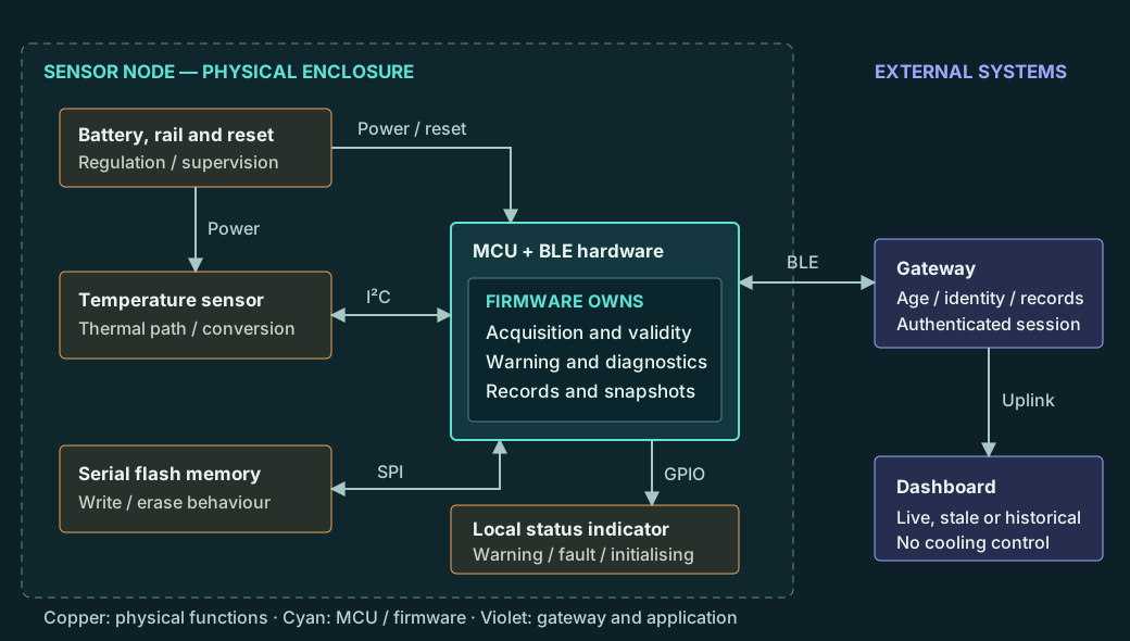
A storage-room temperature node measures once per second, gives a local high-temperature warning, and sends a summary every minute to a nearby Bluetooth Low Energy (BLE) gateway. The gateway forwards records to a dashboard. The node keeps recording when the gateway disappears.
The physical design determines whether the sensor measures the room or heat from its own board. Firmware determines whether a reading is new, valid and timely. The gateway determines whether an old record appears to the user as a current measurement. Each discipline therefore contributes to the trustworthiness of the displayed temperature.
The assumed node contains a battery and regulated supply, voltage supervision, a digital temperature sensor, an MCU with BLE, serial non-volatile memory and a status LED. The sensor is mounted to respond to room air, away from the regulator and radio heat sources. A service connection supports controlled configuration and updates.
Make the initial requirements testable
| ID | Illustrative requirement |
|---|---|
| CS-001 | After thermal equilibrium, indicated temperature error shall be within ±0.5 °C over 0–10 °C in the specified enclosure and operating modes. |
| CS-002 | Initiate one acquisition every 1,000 ms, with at most ±10 ms release jitter against a monotonic schedule. Missed or invalid samples shall be identified. |
| CS-003 | Assert a local warning after three consecutive valid readings ≥8.0 °C. Complete the electronic response within 3.2 s of a sustained qualifying sensor condition. For the specified room-air step from 2 °C to 12 °C, warn within 16 s in the agreed enclosure / airflow conditions. |
| CS-004 | Send a live snapshot and a minute summary every 60 s while connected. The gateway shall mark the live value stale when its conservative age exceeds 90 s. Historical uploads shall not refresh it. |
| CS-005 | Immediately mark an unsuccessful acquisition invalid. Indicate a sensor fault after three consecutive unsuccessful acquisitions, within 3.2 s of a persistent acquisition failure. Continue bounded diagnostics without presenting the last good value as current. |
| CS-006 | Retain at least 24 h of completed minute summaries without a gateway. Retain their identity, order, validity and data-loss indications through reconnection. |
| CS-007 | After supply interruption, preserve previously committed records and configuration. Detect an interrupted write; discard incomplete records. Enter Initialising and obtain three new valid acquisitions before declaring measurements healthy. |
| CS-008 | Support a target 12-month battery interval under the stated normal-use profile. Verify peak-load operation and battery depletion behaviour separately from the average-current estimate. |
| CS-009 | Accept configuration changes only through an authenticated, authorised service session. Validate the complete configuration before committing it and include its version in reported data. |
| CS-010 | Accept only authorised, compatible firmware images. An interrupted update shall retain an approved recoverable image or enter a defined recovery state without claiming live measurements. |
These are a selected system baseline, not a complete product specification. Their identities let the design discussion and verification matrix refer to the same claims. Additional environmental, radio, usability and market requirements would follow from the actual product context.
02 / SYSTEM BOUNDARY
Hardware creates the observation.
Firmware decides what it means.
| Concern | Hardware responsibility | Firmware responsibility | System acceptance |
|---|---|---|---|
| Power / reset | Stable rails, peak-current support, supervision and defined pin states. | Start-up sequencing, reset-cause capture and controlled recovery. | No false healthy state or corruption across the supply fault. |
| Sensing | Thermal placement, sensor operating limits and electrical integrity. | Configured conversion, units, timestamps and validity rules. | Accuracy and response in the assembled enclosure. |
| Interfaces | Levels, pull-ups, routing and optional sensor power isolation. | Bounded transfers, timeout, recovery and atomic data publication. | Correct behaviour under electrical and protocol faults. |
| History | Memory endurance, erase behaviour and power characteristics. | Commit protocol, identity, retention and overflow reporting. | Previously committed records survive interrupted operation. |
| Connectivity | Antenna, radio coexistence and supply behaviour during transmit. | Bounded radio work, access control and data semantics. | Local acquisition remains valid; remote freshness is honest. |
The system owner agrees the acceptance criteria; hardware and firmware owners jointly review each interface contract. Read TEA-101 — Embedded Systems Architecture for allocation and boundary methods.
An energy budget is also a behaviour model.
Use battery-input current so converter losses are already included in the assumed figures. The active currents below are incremental above the 12 µA baseline. Summing them is valid for this illustrative accounting model; real measurements must avoid counting the same load twice. These duty times describe normal use, not worst-case execution bounds.
| Load | Assumed activity | Average contribution |
|---|---|---|
| Sleep, regulation, bias and health indication | 12 µA continuously | 12 µA |
| Sensor conversion | 150 µA for 20 ms each second | 3 µA |
| MCU processing | 4 mA for 5 ms each second | 20 µA |
| Radio activity | 12 mA for 200 ms each minute | 40 µA |
| Record storage | 6 mA for 20 ms each minute; amortised write / erase allowance | 2 µA |
| Total | Normal operation, no active warning | 77 µA |
For a nominal 2,000 mAh battery with 60% assumed usable capacity, the simple estimate is 1,200 mAh ÷ 0.077 mA ≈ 15,584 h ≈ 649 days. This is a feasibility estimate, not a demonstrated service interval. Establish temperature derating, self-discharge, ageing, reconnect activity, alarm duty and the actual battery pulse capability.
If every radio transaction takes three attempts, its contribution rises from 40 to 120 µA. Total current becomes 157 µA and the same estimate falls to about 318 days. An unbounded retry loop can therefore invalidate CS-008 even while every feature appears to work. Set a per-minute radio budget and defer further retries, preserving acquisition and local warning operation.
Peak current and thermal error need separate evidence
During a transmit burst, probe the regulated rail and reset signal at the node. A weak battery can have enough average capacity yet cause a brownout under peak load. At the selected sensor supply, require supervisor thresholds and tolerances that hold the MCU in reset before operation becomes unreliable; numerical thresholds require an actual component selection.
The enclosure also couples radio and regulator heating to the sensor. A provisional steady-state error allocation of 0.20 °C sensor error + 0.05 °C conversion / calibration residual + 0.15 °C installation and self-heating leaves 0.10 °C against the ±0.5 °C limit. Each contribution needs evidence over the stated conditions. Digital resolution alone cannot establish this budget.
TI’s TMP117 data sheet provides a concrete example of conversion-mode, self-heating and layout considerations. It is a reference for the reasoning, not the selected sensor or the source of this case’s assumed 20 ms conversion limit.
“Connected by I²C” is only the beginning.
Select the actual sensor and MCU from a reviewed electrical and timing contract. For this example, the sensor interface is a short, on-board 100 kbit/s I²C bus. Confirm pull-up sizing, line capacitance, logic levels and unpowered behaviour. A transaction acknowledgement shows a transfer response; it does not prove a new, physically correct temperature.
| Contract | Required agreement |
|---|---|
| Sensor start-up | Power-on readiness established before configuration; no assumed-valid register default. Conversion mode is read back where supported. |
| Acquisition | One-shot conversion completes within the assumed 20 ms maximum. A bus transaction has a 2 ms total budget, including software handling; a transfer that exceeds it is invalid. |
| Publication | The acquisition owner publishes value, validity, sequence, conversion start / completion times and configuration version as one coherent object. |
| Recovery | Timeout does not block the scheduler. At most one bounded sensor-recovery sequence per minute; mark data invalid until three successful new acquisitions. |
| Live snapshot | Include device ID, boot ID, sample sequence, value, validity, warning status and age at transmission. A transport acknowledgement does not mean a record is durably stored. |
| Minute summary | Store minimum, maximum, mean, last valid value, valid / expected sample counts and status. A zero-valid-sample minute has no numeric statistics; partial minutes are explicitly marked. |
| Configuration | Validate permissions, ranges and the whole candidate configuration; commit a versioned record before applying it. Reject partially valid changes. |
NXP’s I²C specification, section 3.1.16, distinguishes stuck-SCL and stuck-SDA recovery. Firmware cannot release a physical short by repeatedly retrying a read. If sensor power cycling is part of recovery, hardware must provide it without back-powering through the bus pins.
Keep live data separate from historical delivery
The gateway calculates a conservative live age from the node’s reported age at transmission, elapsed time since reception, a bounded transport allowance and clock uncertainty. The assumed maximum connected-link transit is 500 ms; reject or classify as historical any live message whose timing bound cannot be established. Use monotonic clocks for durations and retain uncertainty in any mapping to UTC.
After a six-hour outage, replayed history must never refresh the live display. Deduplicate durable records using device ID, a non-reused boot ID and record sequence. A new boot ID is allocated through a power-loss-safe mechanism before producing records; otherwise recording remains unavailable. Reset changes session identity, and an old configuration command cannot silently regain authority.
See TEA-104 — Communications Interfaces and Protocols and TEA-204 — Application and Connectivity Engineers for the interface and reconciliation principles.
The electronic deadline starts after a physical assumption.
A slow enclosure cannot be repaired by a faster interrupt. CS-003 deliberately separates the electronic warning rule from the specified ambient-temperature step. For that step only, allocate up to 12 s for thermal transfer until the sensing element reaches the qualifying condition. Confirm the enclosure, placement and airflow; this is not a universal bound for every possible temperature change.
| Contribution | Allocated bound |
|---|---|
| Phase: threshold crossed just after a scheduled sample | 1,000 ms |
| Two further periods for three consecutive qualifying samples | 2,000 ms |
| Absolute schedule release jitter (full ±10 ms range) | 20 ms |
| Final conversion | 20 ms |
| Transfer and coherent publication | 2 ms |
| Decision | 3 ms |
| Indicator update | 5 ms |
| Other bounded interference | 20 ms |
| Electronic allocation / margin to 3.2 s | 3,070 ms / 130 ms |
| Specified physical step: thermal + electronic | 12 s + 3.07 s = 15.07 s, leaving 0.93 s to the 16 s requirement |
The jitter allowance assumes releases tied to an absolute monotonic schedule, not a fresh one-second delay after every task completes. Conversion waiting is non-blocking; flash erases and radio reconnection cannot occupy the acquisition path. If their real interference exceeds 20 ms, the allocation is invalid and the architecture must change.
The local high warning asserts on three consecutive valid values ≥8.0 °C and clears on three consecutive valid values ≤7.5 °C. Invalid samples break both consecutive-value counts; they cannot clear an existing warning. Measurement health, temperature warning and link status are separate state variables so a lost gateway does not masquerade as a normal temperature.
Test the physical step using an independent reference near the sensor location, and test electronic timing with a controlled sensor-interface stimulus. Both are necessary: the latter isolates firmware timing but cannot demonstrate enclosure response. Continue with TEA-105 — Real-time Behaviour.
A believable failure response preserves uncertainty.
| Fault or condition | Detection and response | Recovery / limitation |
|---|---|---|
| Sensor absent or bus stuck | Bounded transfer failure; sample invalid immediately. Three consecutive failures assert the local sensor-fault pattern within 3.2 s. History contains the gap. | Bounded recovery, then three valid new acquisitions. A physical short may need service. |
| Register value stays constant | A constant number alone is not evidence of failure. Track conversion readiness and sequence where supported; challenge with a physical stimulus during verification. | A plausible biased or frozen sensor may remain undetectable without additional independent information. No claim of complete sensor diagnostic coverage. |
| Gateway missing | Acquisition and local warning continue. Store minute summaries; bound radio attempts. Gateway marks its own live display stale after 90 s. | Establish a fresh live snapshot; replay history with original identity without delaying the required live reports. |
| History ring full | Retain the newest window, overwrite the oldest complete record and advance an explicit oldest-record / dropped-record indication. | Never silently imply continuous older coverage. Reconnection reports the gap. |
| Battery warning / brownout | Estimate low-battery condition under defined load; report it while possible. Voltage supervision resets the MCU before unreliable operation. | No guaranteed final radio message. A powerless LED is unavailable, not evidence of a healthy node; gateway stale detection is essential. |
| Reset or interrupted write | Capture reset cause, validate records and configuration, discard incomplete writes and mark the interruption. | Initialising is not Healthy. Obtain three new valid acquisitions; previous measurements remain historical. |
A hardware watchdog is useful only if its servicing demonstrates required progress. The supervisor checks that acquisition attempts, deadline checks and validity publication advance; a diagnosed sensor failure need not cause endless resets. An interrupt that blindly feeds the watchdog can hide a blocked main task.
The LED uses distinguishable Initialising, Healthy, High Warning and Sensor Fault patterns. Fault indication has display priority; retain the temperature-warning status separately in records. A single LED is a limited local interface, so any application requiring assured human response needs a separate usability and risk argument.
With 64-byte committed minute records, 24 h requires 1,440 × 64 = 92,160 bytes. A 128 KiB history allocation has room for 2,048 records, about 34 h before implementation overhead. In an illustrative 256 KiB memory, reserve another 64 KiB for configuration / metadata and 64 KiB for spare / recovery use. Verify the usable ring capacity after sector layout and metadata, not just the nominal chip capacity.
Use pre-erased slots, bounded writes, an integrity check and a durable commit convention appropriate to the selected memory. A CRC detects certain corruption; it does not make writing atomic. Losing power may discard the current uncommitted minute, so mark the interruption rather than promising zero data loss. Assess erase endurance and metadata wear.
Bring up the boundary in observable steps.
| Gate | Experiment and observation | Exit evidence |
|---|---|---|
| 1. Power and reset | Current-limited first power-up; slow supply ramps; transmit-like pulse load. Observe rail, reset and current. | Known board revision; threshold / tolerance review; traces at the permitted limits. |
| 2. Sensor path | Read identity and configuration, trigger conversion, observe bus timing and response to a known thermal stimulus. | Correct units, fresh conversions, timeout and unpowered-sensor behaviour. |
| 3. Local decision | Apply threshold sequences and invalid samples while observing the LED and state record. | Three-sample assertion, hysteresis, fault precedence and timing. |
| 4. Storage | Fill the ring and interrupt writes / erases at defined phases. | Retained committed records, detected gaps and bounded acquisition interference. |
| 5. Connected path | Disconnect the gateway, reconnect with backlog, restart it and repeat acknowledgements. | No duplicate durable records; correct historical / live treatment and freshness. |
| 6. Combined operation | Acquisition, storage, radio retries and low supply together in the assembled enclosure. | Timing, error and power budgets reconciled against representative measurements. |
Retain the exact board, sensor configuration, firmware, bootloader, calibration, gateway and fixture versions. Keep debug-firmware findings separate from release evidence: breakpoints, logging and a powered debug probe can change timing, sleep and supply behaviour. See TEA-108 — Hardware–Software Integration.
08 / REQUIREMENTS TO EVIDENCE
Test the claim at the boundary where it becomes true.
The following is a proposed verification matrix. Every result is Not executed; acceptance criteria below are teaching examples, not measured performance.
| Test / requirement | Stimulus and independent observation | Acceptance / retained evidence |
|---|---|---|
| CS-VT-01 CS-001 | Equilibrate at selected points over 0–10 °C; compare an independent calibrated reference with the assembled node, including radio activity. | Error plus agreed measurement-uncertainty allowance ≤0.5 °C. Retain placement, settling, uncertainty and readings. Example rule: 0.46 °C error + 0.05 °C allowance does not pass. |
| CS-VT-02 CS-002, CS-003 | Instrument acquisition releases; inject threshold crossings immediately after a scheduled sample under maximum allowed radio / storage load. | Absolute release jitter within ±10 ms; three valid readings required; electronic warning within 3.2 s. Capture stimulus, execution and physical LED timing. |
| CS-VT-03 CS-003 | Apply the specified 2 °C → 12 °C air step with controlled enclosure and airflow; use an independent reference and optical LED observation. | Local warning within 16 s from the defined step. Record chamber profile and sensor placement; a register simulator cannot supply this evidence. |
| CS-VT-04 CS-004, CS-006 | Remove the gateway for 24 h; reconnect, replay history, repeat records and restart the gateway during acknowledgement. | Live view becomes stale after conservative age exceeds 90 s; replay never makes it live. All retained records reconcile without duplication; gaps remain visible. |
| CS-VT-05 CS-005 | Disconnect the sensor; force stuck SDA and stuck SCL separately; restore the interface. Independently confirm each injection. | Immediate invalidity; fault after three failed acquisitions within 3.2 s; bounded retries; three valid samples before Healthy. Acquisition supervision continues. |
| CS-VT-06 CS-006, CS-007 | Fill storage beyond its usable capacity; cut power during record write, commit, metadata update and erase. | Committed records remain intact; torn records rejected; explicit gap / overflow status. Capture recovered memory and the expected committed-record set. |
| CS-VT-07 CS-007, CS-008 | Sweep the permitted battery range with representative source impedance, slow ramps and radio bursts. | No operation below the reviewed validity limit; defined reset and restart; no false Healthy indication. Retain voltage, current, reset and state traces. |
| CS-VT-08 CS-008 | Measure the normal-use duty cycle, retry limit, warning duty and service load across relevant temperature and battery conditions. | A documented battery-life argument supports ≥12 months for the stated profile, using justified capacity and ageing assumptions. The 77 µA calculation alone is insufficient. |
| CS-VT-09 CS-009 | Attempt unauthorised, out-of-range and partly valid changes; reset during configuration commit. | Only whole authorised configurations take effect. Previous valid configuration survives interrupted commit; reported configuration identity is correct. |
| CS-VT-10 CS-010 | Try altered, unauthorised and incompatible images; interrupt installation and recovery stages. | Reject invalid images, preserve an approved recovery path and never display unavailable measurements as live. Retain exact image and target identities. |
Give each run an identity and verify the fixture actually applied the stimulus. A missing injection, stale log or disconnected recorder produces invalid or inconclusive evidence, never a pass. TEA-109 — Verification, Debugging and Test Automation explains the evidence method.
The dashboard is current. The measurement is not.
The table below is a fictional trace deliberately constructed to expose a defect. It is not an observation from tested hardware. An acquisition task becomes trapped in a bus driver after a radio-induced supply disturbance, while the communications task continues transmitting.
| Node elapsed time | Event | What the defective system reports |
|---|---|---|
| 10.000 s | Valid sample 410 completes at 6.4 °C. | Measurement valid; temperature below warning threshold. |
| 10.100 s | Radio load disturbs the sensor supply; SDA remains low. | No fault yet. CPU and radio continue running. |
| 11.000 s | Acquisition waits indefinitely inside a transfer. | Cached value remains valid; sequence stays 410. |
| 60.000 s | Communications sends the cached value with a new packet timestamp and a newly fabricated sample age of zero. | Gateway displays 6.4 °C as live. |
| Later | The room temperature rises; no further acquisitions complete. | Repeated packets keep the misleading value apparently fresh. |
Your task
- Identify the violated requirements and the responsibility on each side of the hardware / firmware boundary.
- Explain why packet arrival and a running watchdog do not establish measurement health.
- Propose an electrical fix, a firmware fix and a gateway fix, each with a targeted verification observation.
- Decide whether the evidence is sufficient to identify the electrical root cause.
Show the worked answer
CS-002 and CS-005 fail because acquisition stops without immediate invalidity or bounded fault handling. CS-004 fails because transport time replaces measurement age. CS-003 cannot be relied upon once sensing is unavailable. If the supply excursion violates the reviewed hardware limits, CS-007 / CS-008 evidence also needs reassessment.
Hardware: investigate rail impedance, decoupling, sensor reset and unpowered bus behaviour. The trace establishes correlation, not the cause of the disturbance. Capture sensor supply, MCU supply, reset, SDA and radio activity together, then use a controlled load or supply injection to distinguish hypotheses. Any redesign must be verified under the relevant battery conditions.
Firmware: bound the transfer, invalidate the failed sample, supervise progress and use a recoverable acquisition state machine. Preserve the real acquisition timestamp and sequence; communications must not manufacture validity. A watchdog fed solely by a periodic interrupt can keep running despite this defect.
Gateway: use the validated sample-age and identity contract; receiving a new packet cannot refresh an unchanged historical sample. Challenge repeated sample 410, reconnection replay, changing boot IDs and loss of a trustworthy timing bound. A valid fresh snapshot is needed to restore Live.
Repeat CS-VT-02, CS-VT-04, CS-VT-05 and CS-VT-07 on the affected configuration, with additional regression selected from the actual changes. Success means a bounded, truthful failure response as well as normal recovery; it does not mean hiding the original fault through endless retries.
Review criteria
- Physical measurement, acquisition completion and packet delivery are treated as separate events.
- Every proposed fix has an owner and an observable acceptance criterion.
- The root-cause claim is limited to what the evidence supports.
- Old data and unavailable measurements cannot be presented as healthy live data.
Why does increasing the radio retry limit affect more than connectivity?
It changes energy consumption, supply transients, self-heating and CPU interference. Revisit the battery, accuracy, acquisition and warning arguments together; do not assess only packet delivery rate.
Would replacing the sensor with a more accurate device automatically improve the system?
No. Longer conversion, different start-up, greater self-heating or different fault behaviour can invalidate interfaces and timing. Reassess the complete contract and relevant verification.
Continue across the boundary at The Firmware Academy.
This case establishes system responsibilities and acceptance evidence. The following Firmware Academy lessons explain how to implement the corresponding firmware mechanisms. The temperature-controller project is a related example with an actuator; its numerical requirements and fault policy are different from this sensor monitor.
| System decision here | Implementation learning |
|---|---|
| One owner publishes value, age and validity | TFA-101 — Firmware Architecture |
| Conversion waiting, failed transfers and recovery | TFA-102 — State Machines and Scheduling |
| Absolute scheduling and bounded interference | TFA-103 — Interrupts, Timing and Concurrency |
| Validation, timeouts and meaningful watchdog servicing | TFA-104 — Defensive Programming |
| Authorised images and interruption recovery | TFA-105 — Bootloaders and Secure Updates |
| Fault injection, fixtures and test oracles | TFA-109 — Unit, Integration and HIL Testing |
| Requirements → implementation → tests → release evidence | TFA-112 — Worked Project: Temperature Controller |
Browse the Firmware Academy home page for the full learning library.
Release a known system, with known limits.
A credible release record identifies the board and enclosure, sensor / memory variants, firmware and bootloader, configuration / calibration, gateway compatibility and tested artefacts. It links requirements to evidence and records anomaly disposition, remaining diagnostic limitations and the conditions supporting the battery and thermal claims.
Keep signing keys, device identity and service credentials as separate authorities. Protect configuration changes because they can alter the meaning of reported data. NIST’s Platform Firmware Resiliency Guidelines offer a useful protect, detect and recover perspective for the update design; applicability and implementation still depend on the actual platform.
The next engineering step for this fictional product would be to select components and test the highest-risk assumptions: enclosure thermal response, battery-load behaviour and bounded acquisition during storage / radio activity. A firmware demo alone cannot settle any of those system claims.
References and related learning
- NXP UM10204 — I²C-bus specification and user manualElectrical / protocol behaviour and bus-clear distinctions. Consult the selected component data sheets as well.
- TI TMP117 data sheetAn example of sensor conversion, power, self-heating and thermal-layout considerations; not the component selection for this case.
- NIST SP 800-193 — Platform Firmware Resiliency GuidelinesProtection, detection and recovery concepts for firmware.
- TEA-103 — Sensors, Actuators and Signal AcquisitionMeasurement quality and physical response.
- TEA-106 — Fault Handling and Safe StatesDetection, containment and recovery.
- TEA-111 — Reliability and Lifecycle ManagementMission profiles, field evidence and controlled change.
The components work. Challenge the interfaces.
Put this case study into practice with TEA-402 — Interface and Integration Exercise. Investigate a torn transmission, a lost acknowledgement, stale readings and unexpected restarts. Define the missing requirements, recovery behaviour and integration tests.
Then compare your answer with TEA-403 — Worked Solution, including an example message contract, a recovery state diagram and twelve tests with expected results.
A valid packet is not yet a trustworthy measurement.
The claim becomes credible when power, thermal behaviour, interfaces, acquisition, diagnostics and remote freshness are designed together and verified at their real boundaries.